Encoding & Modulation
Difference between encoding & modulation
Encoding means the process of converting RAW data into a format that can be transmitted through some medium. ex:
- and of Digital world
- Morse Code
Modulation means tweaking that signal in a way so it can be transmitted through the medium. ex:
- If you have to send a signal 5 miles and 5 meters, we have to alter the physical properties such as Frequency, Amplitude etc so the signal does not die when reaching the receiver.
| Question | Encoding | Modulation |
|---|---|---|
| What problem does it solve? | "How do I represent my data accurately without errors or confusion?" | "How do I make this signal physically travel through air, copper, or glass?" |
| Does it need a Carrier Wave? | No. It creates logic pulses, codes, or bit patterns directly. | Yes. It must have an existing high-frequency sine wave to modify. |
| Primary Domain | Digital Logic & Data Formatting. | Electromagnetic Physics & Signal Processing. |
| Analogy | Translating text into Braille or Morse Code. | Flashing a searchlight to beam that Morse code across a bay. |
Main techniques of Encoding
- Digital Data to Digital Signal (Line Encoding)
- Digital Data to Analog Signal (Digital Modulation)
- Analog Data to Digital Signal (Digitization)
- Analog Data to Analog Signal (Analog Modulation)
Polarity of a Scheme
In Signals, polarity is referred to as the sign of "Charge" or "Voltage". ie, direction of the flow. If a voltage level is 0, then it does not have a polarity.
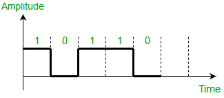
1. Unipolar - One Polarity
In this type, the signal has one voltage direction.
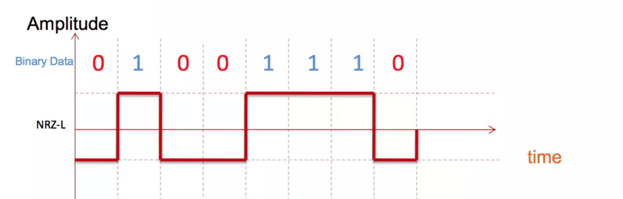
2. Polar - Two polarities
In this case, signal move between two polarities.
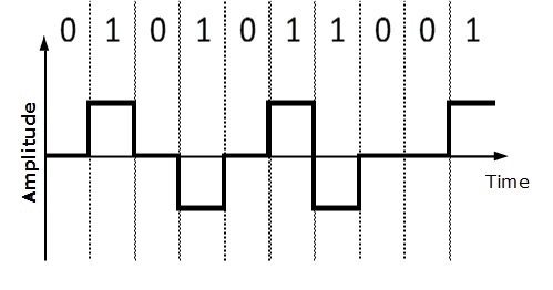
3. Bipolar - Two Polarities + Nuetral
This is similar to #1. Unipolar - One Polarity, So is denoted with no voltage.
Digital Data to Digital Signal
In this case, and will be mapped directly from source to signal.
NRZ vs RZ
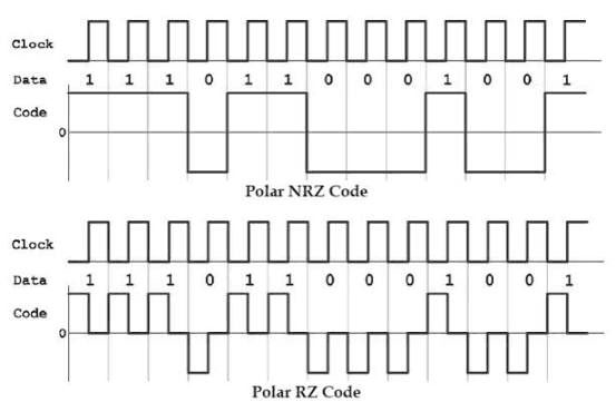
The naming of these two schemes are defined with the question "Does the signal becomes zero in the middle of an interval?" No -> Non Return to Zero (NRZ) Yes -> Return to Zero (RZ)
In RZ schemes, the signal 1 comes down to zero in the middle of interval even when the next bit is 1.
| Scheme | Meaning | Behavior in Middle of Bit Slot | Main Advantage | Main Disadvantage |
|---|---|---|---|---|
| RZ | Return-to-Zero | Always drops to halfway through. | Self-synchronizing (built-in clock). | Requires double the bandwidth. |
| NRZ | Non-Return-to-Zero | Stays flat at the voltage level for the full bit period. | Efficient bandwidth usage. | Synchronization loss on repeated bits. |
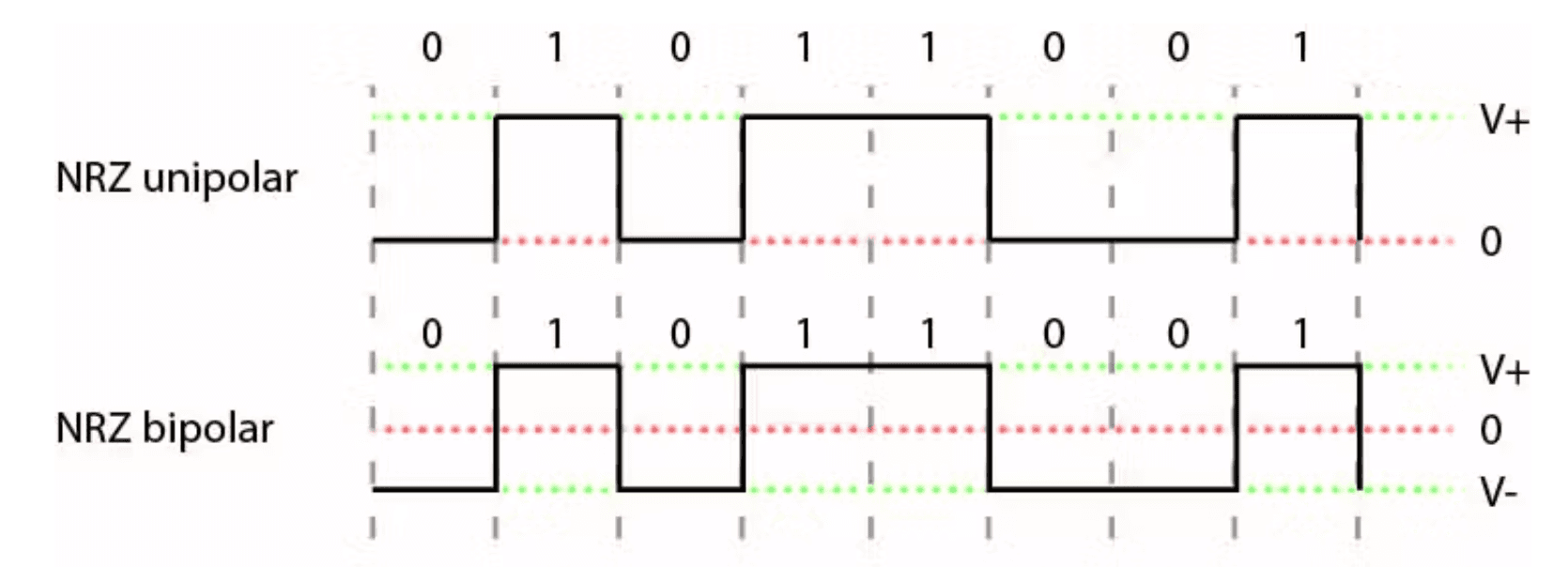
NRZ-L (Level)
In this scheme, Voltage Levels denote bit state. Unipolar - and Polar - and
Main Idea is Level = State
NRZ-I (Inverted)
In this scheme, Voltage Transition at start of an Interval denotes one bit state. This does not mean transition flip bit state, transition means one bit state and no transition means the other bit state.
Transition -> Bit (low to high OR high to low) No Transition -> Bit
Main Idea is Transition = Bit 1
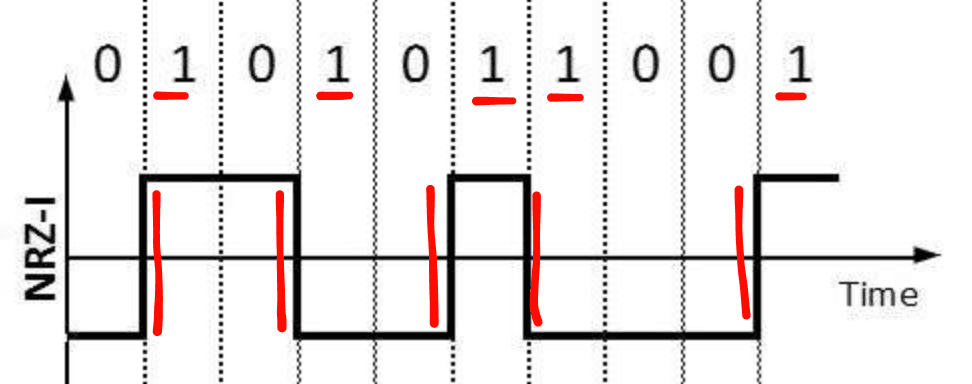
Differential Encoding This is a form of encoding where we use "Transition" from a voltage level to represent one bit state. No transition define the other bit state. rather than using levels directly to represent bit states. NRZ-I is a differential encoding.
Benefits of NRZ schemes
- High use of bandwidth
- Easy to engineer
Issues of NRZ schemes
- has DC component
- This means if a huge sequence of 1s occur in NRZ-L for example, the voltage will be high constant for a long time. resulting in a DC signal.
- In NRZ-I long sequence of 1s avoid this issue, but still 1000000... will do it.
- No synchronization
- RZ schemes avoid this by coming to zero at the middle of interval.
AMI Scheme
AMI - Alternate Mark Inversion, (in early days Mark meant binary )
This is a Bipolar scheme. Adjacent flip voltage while remains 0v.
Advantages
- Main advantage is No DC component as in NRZ, since 1s flip it cancels out over time.
- Also this has built-in error detection. This signal can never have two consecutive same voltage pulses like +1V after +1V So if it happens it is a violation.
Disadvantages
- Does not have a synchronization, same as NRZ
- Long sequence of 0s will fail to detect if signal failure or actual sequence
Pseudoternary
This is basically opposite of AMI. This is also a bipolar signal. Adjacent flip voltage while remains 0v No Advantages over AMI
Tradeoffs of Bipolar signals
- Less efficient than NRZ
- 3 voltage levels can represent bits
- receiver have to distinguish 3 levels
Biphase Signals
These are Special type of Polar Schemes.
- Has two voltage levels
- positive one & negative one
- Has a Mandatory transition in the exact middle of each interval
These are different from RZ schemes (which also have a transition to zero at middle) because RZ uses three levels sometimes.
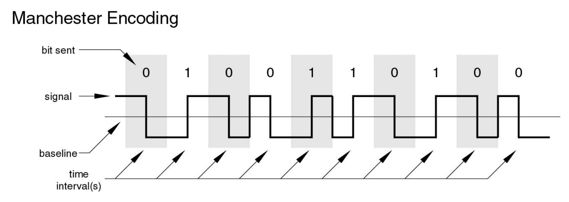
Manchester
This is a biphase scheme. Transition at middle servers as BOTH clock and data.
Low to High High to Low
Used by IEEE 802.3
Differential Manchester
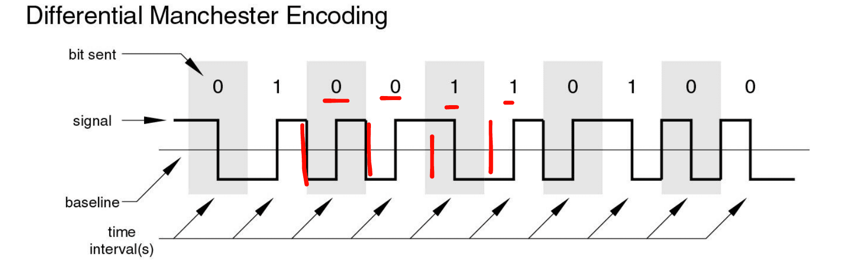
This is a differential biphase scheme. Transition at the start define data. Transition at middle is for clock only.
Transition at start No transition at start
Used by IEEE 802.5
Advantages of BiPhase schemes
- Built-in synchronization
- Error detection
- Missing clock pulse in middle means error
- No DC component in the long average
Cons of Biphase schemes
- Transitions per interval is minimum 1 and max 2
- Modulation rate is twice as NRZ
- More bandwidth needed
Digital Data to Analog Signal
In these we represent digital and states using analog properties (Amplitude, Phase, Frequency)
- Amplitude Shift Keying (ASK)
- Frequency Shift Keying (FSK)
- Phase Shift Keying (PSK)
- Using phase to denote bit, or differential schemes where transition denote one bit
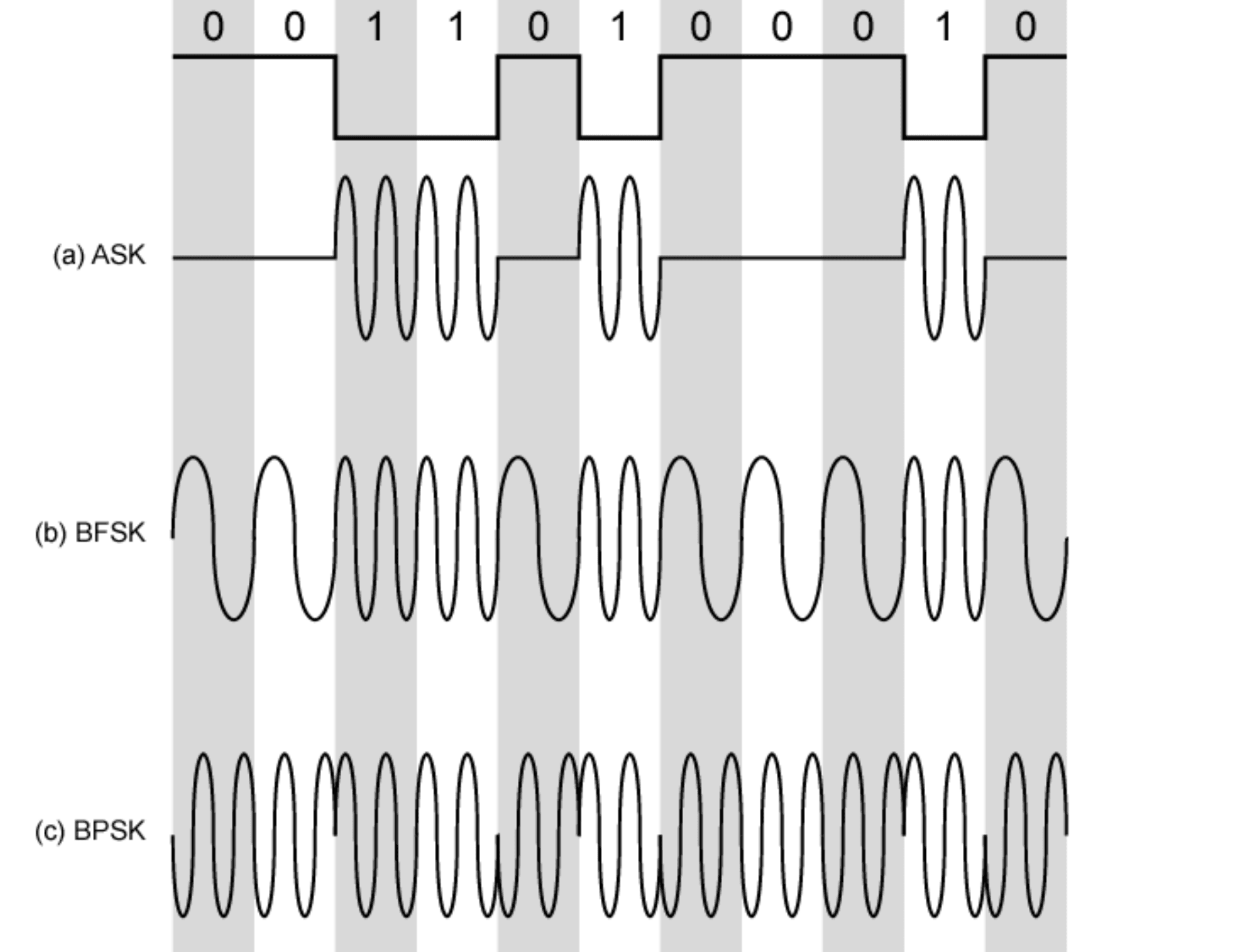
BFSK means binary frequency shift keying. only two frequencies used.
Multiple FSK
This is where Analog transmission shines. You can use multiple frequencies which can result in transmitting more than just a bit at a time. These are more bandwidth efficient.
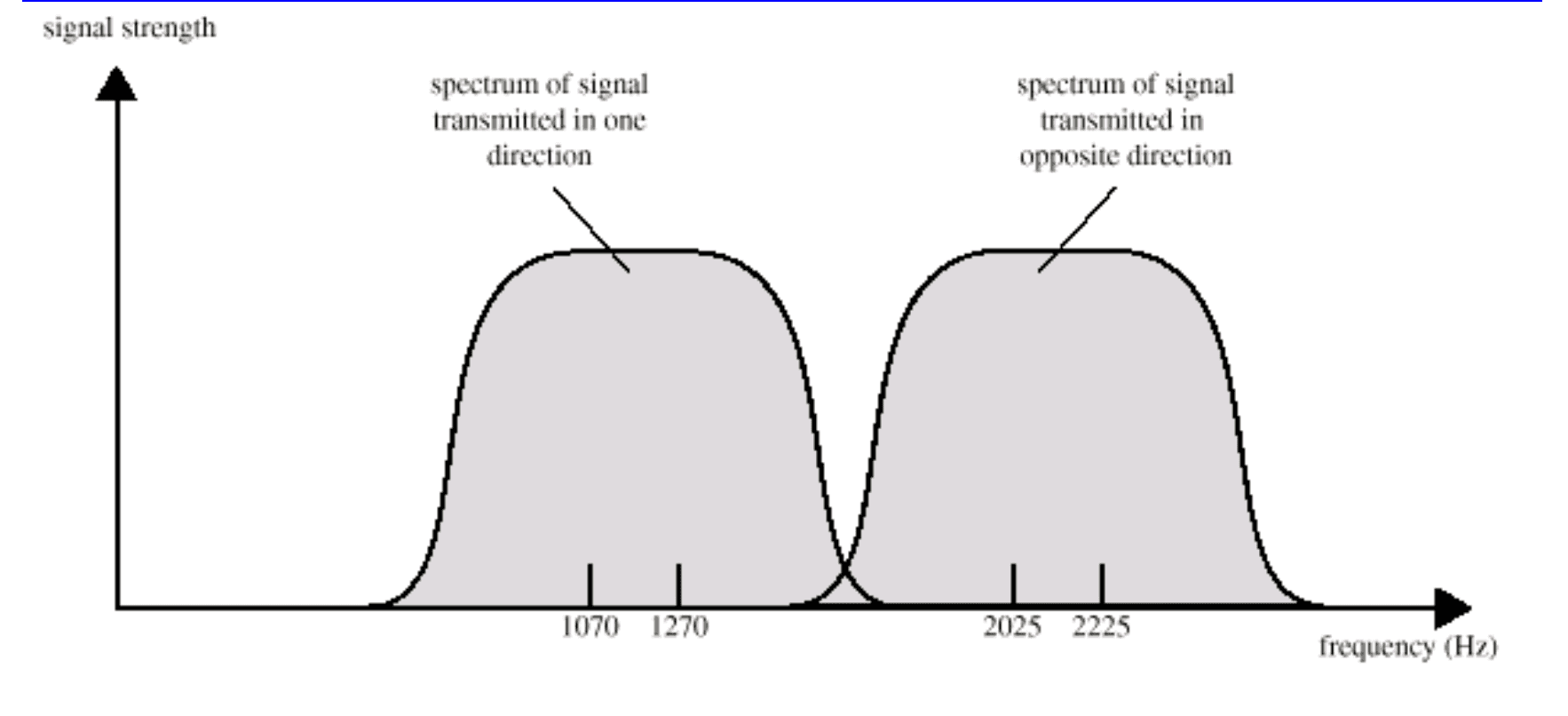
Duplex Transmission
two different range of frequencies used by each party. Which will reduce interference of the signals in voice lines.
Performance of Digital to Analog Modulation Schemes
- Bandwidth
- ASK and PSK bandwidth directly related to bit rate
- FSK bandwidth related to data rate for lower frequencies, but to offset of modulated frequency from carrier at high frequencies
Analog Data to Digital Signal
- AKA Digitization
Transforms Continuous signals such as Distance, Temperature, sound waves into quantized digital units. This is essential for any computations to be done using those.
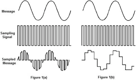
Sampling (Time Discretization)
This is just slicing the signal times per second, we get a discrete set of values from the continuous signal. This is known as the sampling rate/frequency () Usually done at same time interval (),
Nyquist Theorem States that to capture a signal without distortions, we must sample it at least as twice frequency than the max frequency in the signal itself.
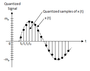
Quantization (Amplitude Discretization)
This is defining different digital states (aka voltage levels) so each signal value can be stored. Using bits, we can define states.
Binary Mapping
This is assigning binary values for each state.
Pulse code Modulation
| Telephony (G.711) | CD Audio | High-Res Audio | |
|---|---|---|---|
| Sampling Rate () | 8 kHz | 44.1 kHz | 96 kHz |
| Bit Depth () | 8 bits | 16 bits | 24 bits |
| Bit Rate () | 64 kbps | 705.6 kbps (per channel) | 2,304 kbps (per channel) |
| ![[pcm.png]] |
Analog Data to Analog Signals
TODO