RISC-V Instruction Format (32bit)
There are 6 Standard Formats, for instructions. RISC-V keeps the critical parts of the instruction in the exact same spot almost every single time.
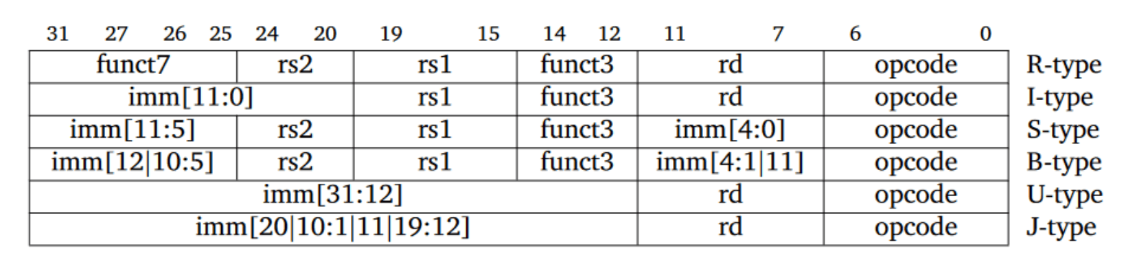
In RISC-V, instructions grouped together like a hierarchy.
| Part | size | Usecase |
|---|---|---|
| opcode | 7bit | These are main groups of opcodes.(like ADD, SUB, XOR, OR, AND, SLL) shares the exact same opcode |
| func3 | 3bit | Submenus of each opcode (uses to get specific instruction) |
| func7 | 7bit | Tie-breakers (helps get more specific instructions if both opcode and func3 are identical. Ex: ADD and SUB) |
| rs1, rs2 | 5bit | Source Registers |
| rd | 5bit | Destination Register |
1. R-type (Register)
Used for Pure Math operations between registers
It takes the data in Source Register 1 (rs1) and Source Register 2 (rs2), performs the math, and saves the result in the Destination Register (rd).
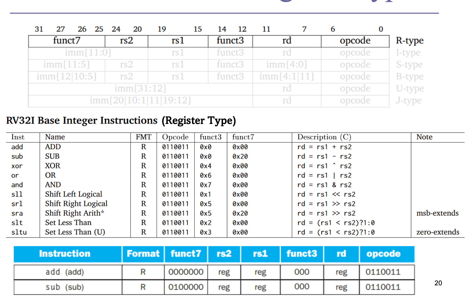
Logical Shift vs Arithmetic Shift
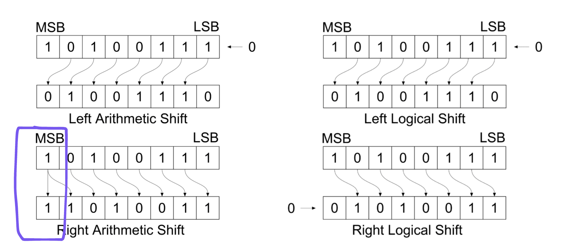
- Right Arithmetic shift preserve sign bit, whereas Right Logical shift can not preserve sign bit.
- Arithmetic shift perform multiplication and division operation, whereas Logical shift perform only multiplication operation.
- Arithmetic shift is used for signed interpretation, whereas Logical shift is used for unsigned interpretation.
2. I-type (Immediate)
Used for math operations that involve a hardcoded number (called an "immediate") or for LOAD instructions from RAM.
Example: ADDI x1, x2, 10 (Add the constant 10 to the value in x2 and store it in x1).
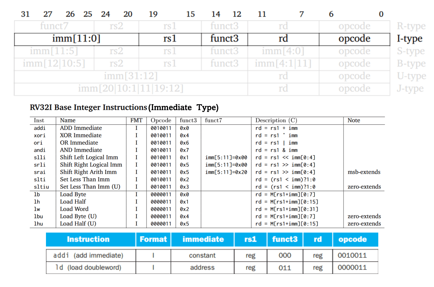
Note:
- uses Sign Extension for filling up bits when loading them to registers
Loadinstructions load data from Memory to registers. They only use Immediate values as memory address finders (like array offsetsarr[imm])
Final RAM Address = Base Register (rs1) + Immediate Value (imm)lbmeans Load Byte (signed) andlbumeans Load Byte (Unsigned)- for instructions like these, the RISC-V 5 Stage Pipeline solution comes in handy
3. S-Type (Store)
these instructions are used to write data back into memory from registers.
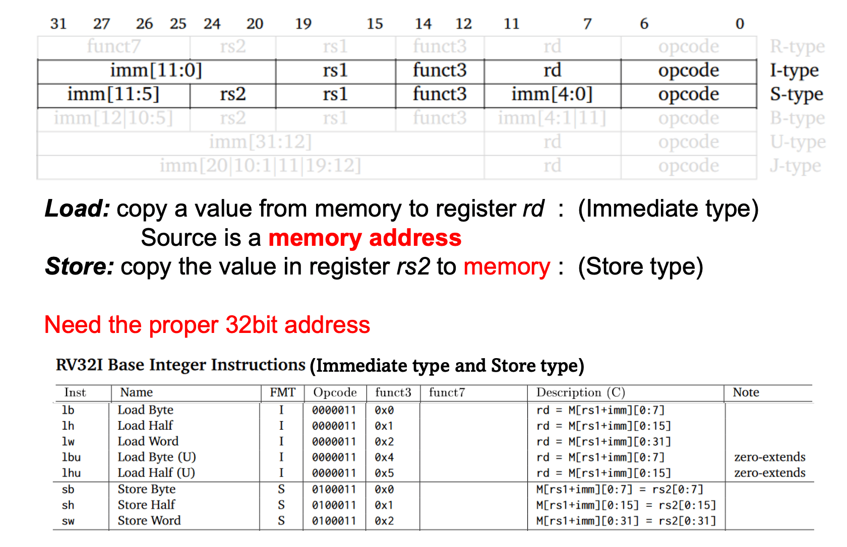
Store instructions need two source registers.
- base address register (
rs1) (this 32-bit register holds the memory address of which the value will be written) - data address register (
rs2) (this 32-bit register holds the data value of which will be written into the memory)
The immediate value is used as the memory offset from the base register's memory address. this is useful for repetitive memory value insertions since we do not need to update the base register address each time Reduces the instruction complexity.
- The immediate value is split into two parts to keep the instruction consistent with other ones. This reduce the hardware design
- (
rs1andrs2are in the exact position in all 32 bit instructions) - The split value will be automatically treated as one in the processor
- 12 bit Immediate value is Signed. Range is
Each store instruction uses the correct potion of the given data register value when storing, such as byte only store the first 8 bits, word store the whole 32 bits
Example: sw x12, 8(x10)
Store word(32-bit) currently in register "x12", to the memory address calculated by adding "8" to the memory address in register "x10"
4. U-type (Upper Immediate)
This type of instructions are designed for loading full 32-bit values into registers. Since the RSIC-V support 32bit instructions, we cannot simply load a 32bit value into registers (since the opcode and other parts should fit into the same 32 bits)
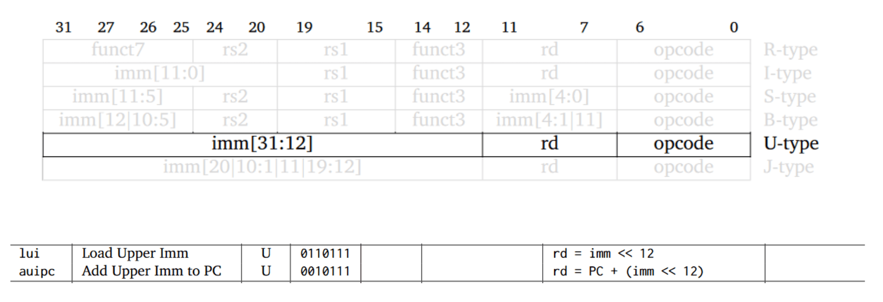
This instruction is really simple since the leftmost 20bits are occupied by the value.
There is a psudo instruction called la (load address) in RISC-V that actually uses auipc and addi instructions to load any value upto 32bits.

Step 1: AUIPC (U-type)
- Calculates the PC-relative offset: .
- Extract the top 20 bits of this offset and loads them into
rd, adding it to the PC. - Formula:
Step 2: ADDI (I-type)
- Extracts the remaining lower 12 bits of the offset and adds them to
rd. - Performs sign-extension compensation automatically if bit 11 of the 12-bit lower offset is .
5. B-Type (Branching)
These are used to alter the execution procedure of the program.
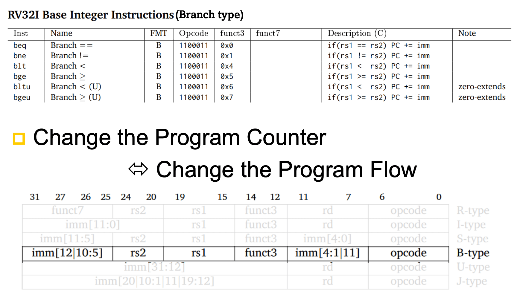
The immediate value is messed up (due to lowering wiring BS).
Note: the immediate of 12bits given in instruction becomes 13bit actual immediate with the last . #Two Byte alignment trick
these branch instructions take two registers and perform some logical operation(equal, greater than, etc). If that operation is true, the branching happens otherwise not.
There are no "less than" instructions. The reason is for simplicity. Less than just means Greater than with the registers swapped. There are pseudo instructions for less than operations but hardware level, everything is greater than.
Simple loop C Code:
C
int count = 10;
while (count > 0) {
    count--;
}
RISC-V Assembly:
Code snippet
    li   t0, 10         # t0 = count = 10
loop:
    blez t0, exit       # If t0 <= 0, jump to exit (pseudo for bge x0, t0, exit)
    addi t0, t0, -1     # t0 = t0 - 1
    j    loop           # Jump back to loop (pseudo for jal x0, loop)
exit:
Branch Addressing
PC relative Branch Addressing
It uses the current PC address as a reference. So its always about how much lines to jump, not the line number to jump. when a branch condition becomes true, the processor compute the new PC Address:
Immediate Offset is a 13-bit signed value.
Two Byte alignment trick
This explains how 12bit instruction value become 13bit
RISC-V requires the Memory to be Byte-Addressed (i.e. addresses points to one byte (8bits)). So 32bit instructions will take 4 bytes for each. So instruction addresses always jump from 4 to 4. In the other hand, the extension C (Compressed) of RISC-V support 16bit instructions, still each instruction address jumps from 2 to 2
This makes every instruction address always even. Which means last bit is always 0. So branching instructions remove it from the actual immediate value and put it back as its an implicit value. This allows the instruction offset to go from 12bit to 13 bit, Branch offset range of to bytes.
6. J-type (Jump)
this just jumps to the given location without checking nothing. Jump instructions are in two types. one in I type and other one is in J type.
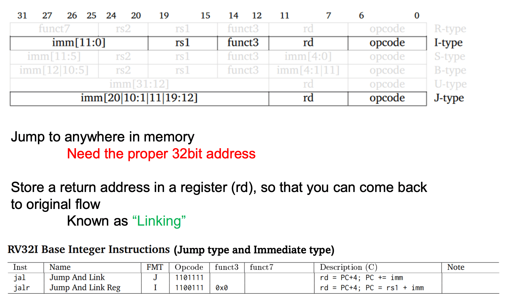
Note: Jump instruction also being used in functional/procedural calls and returns because it saves the return address into register.
Linking?
jal - Jump and Link
In these instructions, Linking means, it stores the next instruction in the instruction sequence (before jumping) to the destination register rd
This is useful when the jump happened and all the instructions executed in the jump and it needs to return to the original place (which is PC + 4 bytes)
This is how functions work.
If the linking is not required, we can pass x0 as the rd register value, it will just ignore it.
J-type (JAL - Jump and Link)
jal x1, label
This uses PC relative addressing same as Branch instruction. This also uses the 2 Byte alignment trick. (Lowest byte of offset is always implicit and its )
Support 21-bit range using 20-bit address ( range from current PC)
Operation:
I-type (JALR - Jump and Link Register)
jalr x0, 0(rs1)
Key difference: This one get destination address dynamically using value in rs1 and a immediate offset. (Not the PC and Immediate offset)